Chapter 15 Electromagnetism (Long Questions)
15.1. Demonstrate by an experiment that a magnetic field is produced around a straight current-carrying conductor.
15.2. State and explain the rule by which the direction of the lines of force of the magnetic field around a current-carrying conductor can be determined.
15.3. You are given an unmarked magnetized steel bar and bar magnet, its north and south ends are marked N and S respectively. State how would you determine the polarity at each end of the unmarked bar?
15.4. When a straight current-carrying conductor is placed in a magnetic field, it experiences a force. State the rule by which the direction of this force can be found out.
15.5. State that a current-carrying coil in a magnetic field experiences a torque.
15.6. What is an electric motor? Explain the working principle of D.C motor.
15.7. Describe a simple experiment to demonstrate that a changing magnetic field can induce e.m.f. in a circuit.
15.8. What are the factors which affect the magnitude of the e.m.f. induced in a circuit by a changing magnetic field?
15.9. Describe the direction of an induced e.m.f. in a circuit? How does this phenomenon relate to conservation of energy?
15.10. Draw a labelled diagram to illustrate the structure and working of A.C generator.
15.11. What do you understand by the term mutual induction?
15.12. What is a transformer? Explain the working of a transformer in connection with mutual induction.
15.13. The voltage chosen for the transmission of electrical power over large distances is many times greater than the voltage of the domestic supply. State two reasons why electrical power is transmitted at high voltage.
15.14. Why is the voltage used for the domestic supply much lower than the voltage at which the power is transmitted?
CONCEPTUAL QUESTIONS
15.1. Suppose someone handed you three similar iron bars and told you one was not magnet, but the other two were. How would you find the iron bar that was not magnet?
15.2. Suppose you have a coil of wire and a bar magnet. Describe how you could use them to generate an electric current.
15.3. Which device is used for converting electrical energy into mechanical energy?
15.4. Suppose we hang a loop of wire so that it can swing easily. If we now put a magnet into the coil, the coil will start swinging. Which way will it swing relative to the magnet, and why?
15.5. A conductor wire generates a voltage while moving through a magnetic field. In what direction should the wire be moved, relative to the field to generate the maximum voltage?
15.6. What is the difference between a generator and a motor?
15.7. What reverses the direction of electric current in the armature coil of D.C motor?
15.8. A wire lying perpendicular to an external magnetic field carries of a current in the direction shown in the diagram below. In what direction will the wire move due to the resulting magnetic force?
15.9. Can a transformer operate on direct current?
15.1. Demonstrate by an experiment that a magnetic field is produced around a straight current-carrying conductor.
Ans. Current carrying conductors in opposite directions. In both cases, the current carrying conductor is intercepted by a cardboard placed at right angles to the current carrying conductor.
- There are some iron fillings sprinkled on the conductor.
- When current flows through the conductor, the iron filing arrange themselves along the magnetic field.
- We can see that the magnetic field in both cases is in opposite directions as is the current.
- The magnetic field produced by a current-carrying straight wire depends inversely on the distance from it and directly on the current passing through it.
- From this we see that the current carrying conductor produces a magnetic field around it. The direction of this magnetic field is given by Right Hand Thumb Rule.
Right Hand Thumb Rule
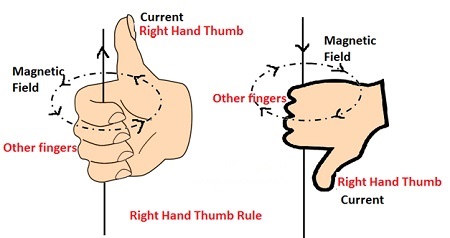
Suppose that you are holding a current-carrying straight conductor in your right hand such that the thumb points towards the direction of flow of current. Then, your fingers which wrap around the conductor indicate the direction of magnetic field lines (as shown in the figure)
15.2. State and explain the rule by which the direction of the lines of force of the magnetic field around a current-carrying conductor can be determined.
Ans. Right hand rule is used to determine the direction of a magnetic field lines relative to the direction of conventional current. “Grasp the straight conductor in our right-hand with the stretched thumb along the direction of the conventional (positive) current. The curling finger of the hand will point in the direction of the magnetic field.
15.3. You are given an unmarked magnetized steel bar and bar magnet, its north and south ends are marked N and S respectively. State how would you determine the polarity at each end of the unmarked bar?
Ans. Bring the north pole of bar magnet near one end (1st face) of unmarked magnetized steel bar.
- If they attract each other, then this face of steel bar is south pole.
- If they repel each other, then this face of steel bar is north pole.
Mark this face with north or south accordingly and repeat the above exercise to mark the 2nd face of magnetized steel bar.
15.4. When a straight current-carrying conductor is placed in a magnetic field, it experiences a force. State the rule by which the direction of this force can be found out.
Ans. The direction of the force on a current-carrying conductor is determined by the Fleming’s left hand rule.
Fleming’s Left Hand Rule:
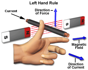
It states that “Stretch the thumb, forefinger and the middle finger of the left hand mutually perpendicular to each other. If the forefinger points in the direction of the magnetic field, the middle finger in the direction of the current, then the thumb would indicate the direction of the force acting on the conductor.
15.5. State that a current-carrying coil in a magnetic field experiences a torque.
Ans. If a coil carrying a current is placed in a magnetic field it will experience a force on two of its sides in such a way as to make the coil rotate. This effect is the basis of all electric motors and moving coil meters. Think of all the places where electric motors are used from stereos, disc drives, CD players, starter motors in cars, washing machines etc. etc. and you will realize how important this effect is? The forces are shown in Figure.
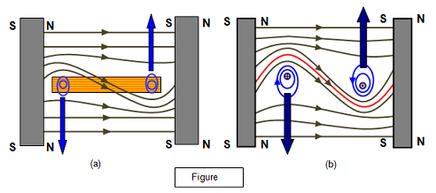
You can see why the coil will rotate from the ‘double catapult’ field diagram in Figure (b). Since the current moves along the two opposite sides of the coil in opposite directions the two sides receive a force in opposite directions also, thus turning the coil.
Mathematical consideration
Formulae for the force on a coil in a magnetic field
Consider a rectangular coil with sides of length a and b placed in a magnetic field of flux density B and free to rotate about an axis perpendicular to the paper, current of I Amps flows in the coil.
The field exerts a force on the sides b given by
Force (F) on side length b = BNIb
where N is the number of turns on the coil.
If the perpendicular to the coil is at an angle θ to the field direction, then the torque exerted on the coil is Fd where d = a sin q.
Therefore the torque C is given by:
Torque (C) on the coil = Fa sinθ = BNIba sin θ or:
Torque (C) on the coil = BANI sinθ
where A = ab, the area of one face of the coil.
The maximum torque occurs when the plane of the coil is lying along the field lines (θ = 90o and sin q = 1). At this point, shown in Figure (a).
Maximum torque (Co) = BANI
The minimum value of the torque is zero, when θ = 0.
15.6. What is an electric motor? Explain the working principle of D.C motor.
Ans. An electric motor is an electrical machine that converts electrical energy into mechanical energy. General-purpose motors with standard dimensions and characteristics provide convenient mechanical power for industrial use.
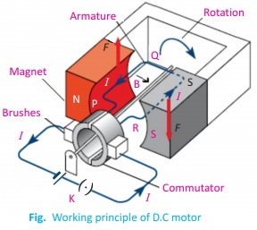
Working principle of D.C motor
A current-carrying conductor will experience a force when placed within a magnetic field. The principle of the electric motor is that it converts electrical energy into kinetic energy (mechanical energy) through the interaction of the two magnetic fields.
A simple DC motor uses a stationary set of magnets in the stator, and a coil of wire with a current running through it to generate an electromagnetic field aligned with the center of the coil. The commutator allows each armature coil to be energized in turn, creating a steady rotating force (known as torque).
15.7. Describe a simple experiment to demonstrate that a changing magnetic field can induce e.m.f. in a circuit.
Ans. When a magnet is pushed into the solenoid, there is a change in magnetic field lines linking the solenoid, which produces an induced e.m.f. This induced e.m.f. drives a current in the circuit, causing the pointer of the galvanometer deflects momentarily.
- When the magnet is stationary, there is no change in magnetic field lines linking the circuit. There is no induced e.m.f. and hence no current detected by the galvanometer.
- The experiment show that induced current (or induced emf) is produced in the coil due to the changing magnetic field in the solenoid. This process is called electromagnetic induction.
- The factors affecting the magnitude of the induced emf can be demonstrated as follows:
a. When the magnet moves at a faster speed in or out of the coil, the magnitude of the induced current is increased.
b. When a stronger magnet is used, the magnitude of the induced current is increased.
c. When the number of turns in the coil is increased, the magnitude of the induced current is increased.
15.8. What are the factors which affect the magnitude of the e.m.f. induced in a circuit by a changing magnetic field?
Ans. Factors:
Following are the factors which affect the magnitude of the induced emf in a circuit.
- Speed of relative motion of the coil and the magnet.
- Number of turns and area of cross-section of the coil.
- Amount of current passing through the coil.
15.9. Describe the direction of an induced e.m.f. in a circuit? How does this phenomenon relate to conservation of energy?
Ans. The direction of induced emf and induced current is determined by Len’s law which states. The direction of the induced current is always such that it opposes the cause that produces it.
The induced emf is produced by the changing of magnetic flux in the circuit. The magnetic flux is changed by applying mechanical energy. So one kind of energy is going to change into electrical energy. Hence this phenomenon is in accordance with the conservation of energy.
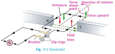
15.10. Draw a labelled diagram to illustrate the structure and working of A.C generator.
Ans. A simple AC generator consists of a rectangular coil ABCD which can be rotated rapidly between the poles N and S of a strong horseshoe-type permanent magnet M. The two ends A and D of the coil are connected to two circular pieces of copper metal called slip rings R1 and R2
15.11. What do you understand by the term mutual induction?
Ans. Mutual-induction: The phenomenon of production of induced emf in one coil due to change of current in a neighboring coil is called mutual induction.
The SI unit of mutual induction is “Henry”. Its mathematical form is given as
M = – (emf)s * Δt/ΔIp
Negative sign is the due to Len’s Law.
Where “M” stands for mutual induction, S for secondary coil across which emf is being generated due to rate of change of current in primary (P) coil.
Henry:
The mutual inductance of two coils is said to be one “Henry”. If a current changes at the rate of one ampere per second in the primary causes an induced emf of one volt in the secondary coil.
15.12. What is a transformer? Explain the working of a transformer in connection with mutual induction.
Ans. Transformer: The transformer is a practical application of mutual induction. Transformers are used to increase or decrease AC voltages. Usage of transformers is common because they change voltages with relatively little loss of energy. In fact, many of the devices in our homes, such as game systems, printers, and stereos use transformers for their working.
Working of a transformer
A transformer consists of two electrically isolated coils and operates on Faraday’s principal of “mutual induction”, in which an EMF is induced in the transformers secondary coil by the magnetic flux generated by the voltages and currents flowing in the primary coil winding.![]()
Vs/ Vp = Ns/Np
If the secondary voltage is larger than the primary voltage, the transformer is called a step-up transformer. (Fig (a))
If the secondary voltage is smaller than the primary voltage, the transformer is called a step-down transformer. (Fig (b))
In an ideal transformer, the electric power delivered to the secondary circuit is equal to the power supplied to the primary circuit. An ideal transformer dissipates no power itself, and for such a transformer, we can write:
15.13. The voltage chosen for the transmission of electrical power over large distances is many times greater than the voltage of the domestic supply. State two reasons why electrical power is transmitted at high voltage.
Ans. Electric power of transmission is the bulk movement of electrical energy from power station to electrical substation. Power is transmitted at higher voltage to reduce power losses during transmission. Power is the product of voltage and current.
P = VI
I = P/V
So when the same amount of power is transmitted at high voltages, current in the conductor should be low. This leads to less power loss in the power lines. Since power loss is proportional to the square of current.
P = I2R
So, for the same value of R and Power, Power losses is less if current is less this can be achieved by transmitting power at high voltages.
15.14. Why is the voltage used for the domestic supply much lower than the voltage at which the power is transmitted?
Ans. The voltage used for the domestic supply are much low.er because voltage is stepped down and is transmitted to the city sub-station. All the house- hold appliances operate on 220V.
15.1. Suppose someone handed you three similar iron bars and told you one was not magnet, but the other two were. How would you find the iron bar that was not magnet?
Ans. There are two methods to identify that which iron bar is not magnetic.
Method-I
Having three similar iron bars in hand bring them close to each other one by one and from both ends separately. The iron bars will being attracted but not repelled by any end of the others two bars. This will be the iron bar.
Method-II
Having three similar iron bars in hand bring them close to a compass needle one by one. In case of magnetic bar the compass needle will det1ect due to the presence of other magnetic field but there is no deflection in case of iron bar.
15.2. Suppose you have a coil of wire and a bar magnet. Describe how you could use them to generate an electric current.
Ans.
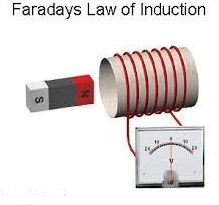
From figure this is called as Faraday’s laws of electromagnetic induction which states that when a magnetic flux linked with the coil changes, there’s an emf that is induced in the coil.
Now if you want to generate electricity, just move the magnet in and out at a regular interval and you will see the coil of galvanometer is moving which means electricity is produced. If instead of this galvanometer, you connect an LED, it will glow; maybe dimmer than what you expect but electricity will be produced.
15.3. Which device is used for converting electrical energy into mechanical energy?
Ans. A device which converts electrical energy into mechanical energy is called an electrical motor. The working principle of an electric motor depends on the magnetic and electric field interaction.
15.4. Suppose we hang a loop of wire so that it can swing easily. If we now put a magnet into the coil, the coil will start swinging. Which way will it swing relative to the magnet, and why?
Ans. The loop will swing (to and fro) having the magnet at the mean position. On swinging the magnetic flux through the coil will change.
According to Faraday’s law induced current will flow. According to Len’s law, on either extreme position the current will adopt the direction to oppose the cause producing it. So from extreme it will move towards mean. From mean to other extreme due to inertia and then again from extreme to mean due to induced current opposing the cause it. In this way it will swing.
15.5. A conductor wire generates a voltage while moving through a magnetic field. In what direction should the wire be moved, relative to the field to generate the maximum voltage?
Ans. When the wire moves in the perpendicular direction to the magnetic field. Then maximum voltage will be generated.
15.6. What is the difference between a generator and a motor?
Ans. Motor: An electric motor is a machine that converts electrical energy to mechanical energy. Electric motor follows Fleming’s left-hand rule.
Examples: Ceiling fans, cars, etc. are all examples of motor.
Generator: An electric generator is a machine that converts mechanical energy to electrical energy. Electric generator follows Fleming’s right-hand rule.
Examples: In power stations, generator is used to generate electricity.
15.7. What reverses the direction of electric current in the armature coil of D.C motor?
Ans. The split rings a circular shape that split up into two halves. When the armature rotates to vertical position from horizontal the gaps between split rings and their connection with the coil is cut off, no torque is acting on the coil but due to inertia it goes through 180°. And connection of brushes again becomes with the split rings now the brush X is connected with S2 and Y is connected to S 1. So the direction in the coil is reversed due to which the coil continue its rotational motion in clockwise direction.
15.8. A wire lying perpendicular to an external magnetic field carries of a current in the direction shown in the diagram below. In what direction will the wire move due to the resulting magnetic force?
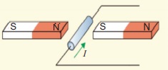
Ans. According to the Fleming’s left hand rule, the direction of the force will be downward.
15.9. Can a transformer operate on direct current?
Ans. A transformer cannot operate on direct current because direct current gives constant magnetic flux. According to Faraday’s law induced emf produces only when there is the change of magnetic flux.